


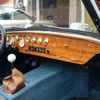
The original dashboard has been repaced with a full width dashboard of my design. The new design provides optimal instrumentation placement and aesthetics. The new dashboard design includes the electrical connections to the existing wiring using military connectors - it allows the removal of the dashboard for maintenance and any future improvements. The new dashboard is crafted from Hawaian Koa wood by Prestige Autowood of San Jose.
I drew a set of electrical schematics to specify the wiring additions and modifications required for the project. Many past additions to the car - electric water pump, electric fans, indicator lights, and much more - created a chaotic web of added wiring under the dashboard. It looked like it was a colored web woven by a hallucinating spider.
I designed an interface board to which all wires from the chassis and body are connected. The interface board includes connector strips for grounding, 12 volt switched power, all sensors, and all switched devices. The interface board is then connected to the dashboard by two military connectors. This makes it easy to remove the dash for future mods to the Spitfire and maintenance - and, corrects the messy wiring under the dashboard.
A new dash pad was created to replace the sun-baked, cracked original and is the same color as the Miata seats that are installed in the car.
The photos in the above slideshow provide a visual record of the installation. The photos are arranged to support the installation phases. Put the slideshow on manual by clicking on the 'Next' command and access the photos as they are introduced in the narrative.
- Design & FabPhoto 2: Shows the accurate template I created. The template was based on the outline of a newer model Spitfire' dash - this assured an accurate fit. The functionality and layout of the new dashboard supports the existing functions of the stock Spitfire - speedometer, tachometer, oil pressure gauge, ignition switch, fuel gauge, water temperature gauge, amp meter, volt meter, analog clock, windshield wipers, dash lights, turn signal backup, high beam indicators, 12 volt switched power source and additions made to the Spitfire such as the twin SPAL electric fans, Moroso electric water pump, and Carter electric fuel pump. The dashboard is designed to for easy removal to facilitate making future mods, or performing maintenance.
Photo 3: Shows the completed dash fabricated by Prestige Autowood, of San Jose. It was created out of Hawaiian Koa Wood. It was then populated with the gauges, switches, indicators, and other items.
Photo 4: Shows the new dashboard schematic. The schematic was continually revised during installation to make sure it was a true record of how the dash was designed.
Photo 5: Shows the dashboard with wiring completed in accordance to the new schematic. It was given wiring continuity checks then powered up and tested to assure its functionality.
Photo 6: Shows the front view of the completed dashboard. - Electrial Interface - Dashboard to ChassisPhoto 8: Shows the schematic that governs the function of the interface board. It represents the connectivity of the chassis to the new dashboard. Using an interface board between the chassis and the new dashboard makes it possible to have a removable dashboard.
Photo 9: Shows the completed diagram of the interface board including where the military connectors will be connected. - Label or Remove Existing WiresPhoto 11: Shows the spider nest of added wiring. The first step was to identify and label those wires that will remain. Those that are not labeled are not needed and will be removed as the interface board is wired.
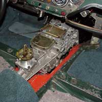
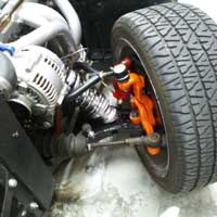
Photo 12: Shows an initial interface board containing just the switched 12 volt power. This was a proof of concept check. - Front Steering Column Support ModificationPhoto 14: Shows the side view of the stock installation of the front steering column support. It was necessary to move the column support to create more room for the new dashboard's speedometer, fuel gauge, and tachometer.
Photo 15: Shows the side view of the repositioned front steering column support. In order to create the space for the new dashboard, the steering column support was turned around front to back. It was pushed back about 2.5 inches.
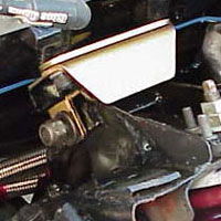
Photo 16: Shows a front view of the repositioned steering column support. - Remove Old Dash PadPhoto 18: Shows the windshield frame raised 1 1/2 inches to allow the removal of the existing dashpad.
Photo 19: Shows The original dashpad with the windshield blower ports and ashtray removed. - Remove Old DashboardPhotos 21& and 22: Show the old dash removed.
Photo 23: Shows a comparison of the old dash to the new dash. - Modify & Redress Wiring HarnessPhoto 25: Shows behind the existing dash with test interface board before removal of the old dashboard frame and the rest of the unecessary wiring.
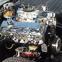
Photo 26: Shows the redressed wiring bundle in the engine compartment as it passes through the firewall to the interior.
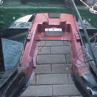
Photo 27: Shows the wiring bundle as it passes into the interior of the car. These new and remaining wires will be attached to the full interface board. - Remove Old Dashboard's FramePhoto 29: Shows the old dash frame removed along with the old dash and a small two gauge frame.
- Complete Interface Board WiringPhoto 31: Shows the two military connectors wired to the interface board.
Photo 32: Shows the interface board mounted and the attaching of most of the Spitfire's chassis wires. - Install GPS Speed SensorPhoto 34: A VDO speed sender, using GPS technology to sense a car's speed, was selected to provide the VDO speedometer with speed data. This approach is much more accurate than a transmission mounted sender. And, it does not require transmission and differential gear ratios, nor tire diameter for calibration.
Photo 35:Is a closer look at the GPS sender mounted in the dash top - where the ashtray used to be. The dashpad will be glued to the dashtop and help to hold the sender mount in place. - Install New Dashboard FramePhoto 37: Shows the new dashboard frame installed.
Photo 38: Shows one of two braces to secure the dash frame. This one is attached to the modified steering column support.
Photo 39: Shows the second brace on the passager side of the Spitfire is mounted to the firewall. These braces make the new dashboard fully stable.Install New DashboardPhoto 41: To check the fit, the dashboard template was set in place - no adjustments were required.
Photo 42: Shows the new dashboard's initial installation. After a couple of mounting screw adjustments, it fit perfectly.
Photo 43: Shows the complete mounted dashboard. Still to be electrically connected to the interface board with the military connectors and tested.
Photo 44: Shows the interior back together after dashboard installation. The old, cracked ( 54 years old ) dash pad has been replaced.
Photo 45: I found a British car restoration business, British Steel of Fresno, that could work with the dashpad. The owner Rick Rogers, his upholstery guru, Bill, and I discussed it and they said it would be easier to create a custom pad. Now I could get it exactly as I wanted it - make it from the same colored naugahyde that my Miata seats were covered in and create a shifter boot from the same material. I told them where I wanted the VDO GPS speedometer sender mounted.
Photo 46: At completion, it was awsome. The color of the naugahyde made the Koa wood of the dash really stand out and I was finally rid of the ugly rubber shifter boot.Resolve Installation IssuesAt this stage the dashboard has been electrically connected and tested.
There were several electrical issues to be resolved.
The second issue was that the tachometer required the adjustment of the set of mini switches - to do this, I had to remove the dashboard. The capability to remove and replace the dashboard proved very helpful. After setting the switches, the tachometer operated correctly.
In order to check the calibration of the speedometer and tachometer, I created a web page that calculates the speed, MPH, and the engine revolutions, RPM. It takes into account the transmission gearing, differential gearing, and tire diameter. Just enter either the target MPH, or engine RPM. Comparisson of the outcome of the calculations with the input of the GPS signal proved the calibration of the speedometer and tachometer. This web page is accessible via the Ye-Beast website for visitors to use.
The third issue was the fuel level sender did not work in conjunction with the VDO fuel gauge. The solution was to take a brand new fuel level sender from British Victoria and combine it with the VDO sender rheostat that is matched to the VDO fuel guage in the dashboard. It required one adjustment after the initial use - not a fun thing to work on since you have to pump out the tank every time a test, or adjustment has to be performed.Updated: Fri 16 Apr 2021