
This slideshow depicts the stages of the installation of the Tremec 3550 transmission. The Tremec is much larger than
the Muncie 4-spd that it is replacing. The installation required frame modifications as well as custom mounting solutions. It would be best to advance through the photos manually when following the explanations for each step.
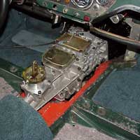
Photo 1 shows the removal of the Muncie 4 spd. Since the combined size of the engine and transmission when connected is too large for them to be installed or removed together, the transmission has to be removed and installed from the interior of the car.
Photo 2 shows the new Tremec in its shipping crate - bottom side.
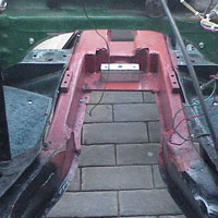
Photo 3 shows the frame prior to the installation of the Tremec transmission. Modifications will have to be made in order for the tremec to fit.
Photo 4 is a closeup of the area where the modifications are to be made. The area between the rails, where the frame is already relieved needs to be widened even more. This caused me concern - would this weaken the frame, maybe causing it to bend? The modifications would require the rebuilding of the box nature of the frame structure. I calculated the area of the cross section of the frame and determined the thickness of the new materials required to give the same cross sectional area of material. I manufactured the pieces and took them to a shop that creates race cars from the frame/cage up and had them do the modifications and welding.
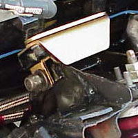
Photo 5 shows the modifications that allow the Tremec to fit. The frame relief shown in photo 3 was increased to allow a wider and deeper transmission casing. The stock cross-brace was channeled for the Tremec tail housing. As stated prior to this photo, the new
walls of the frame were reconstructed using 1/4 inch steel.
Photo 6 shows an adaptor I made required to move the transmission rear mount forward 1/2 inch. I used 1/4 inch steel for this piece.
Photo 7 shows the adaptor mounted on the Tremec.
Photo 8 shows the Tremec rear mount attached to the adaptor.
Photo 9 shows the Tremec rear mount adaptor required to raise the tail-shaft of the transmission to its proper height. I had my brother-in-law's machine shop make it.
Photo 10 shows the rear mount adaptor installed on the frame.
Photo 11 shows a McLeod hydraulic throwout bearing mounted on the Tremec. The bearing repaces the existing bearing retainer and must have the correct amount of 'crush' pressure on the retaining rings. At first the bearing did not fit as advertised - I assumed that they may have used a different version of the Tremec. I contacted McLeod and explained the situation and they had me ship it back with my findings and re-machined it. This photo shows the corrected bearing mounted on the Tremec.
For whatever reason, I had to make a modification to allow the for an extra 1/8 inch clearance of the pilot shaft. I had my brother-in-law's machine shop create a spacer out of 1/8 inch aluminum to place between the bell housing and the transmission.
Photo 12 shows the Tremec installed.
Photo 13 shows the sheet metal tunnel extension installed over the driveshaft.
Photo 14 shows carpeting cut and installed over the tunnel extension. This will have to be removed for the fabrication of the forward section of transmission tunnel.
Photo 15 shows the fabrication of the forward section of the transmission tunnel. Since I had to do the same thing for the Muncie transmission, I started with the forward part of the existing tunnel and refabricated the section that would cover the new, much larger Tremec. The material that I used was poster board. I taped it together to make the tunnel fit the shape of the Tremec. Then used an embedded metal strip that fit the curvature of the sheet metal tunnel extension.
Photo 16 - Next came three to four layers of fiber glass on both sides of the tunnel.
Photo 17 shows the application of a material to insulate from heat and soundproof the tunnel. Great stuff. I used it in the doors of the car to make the doors sound more substantial.
Photo 18 shows the addition of fiberglass to the tunnel that custom fits it to the floor panels to stop air flow from under the car to the interior. The tunnel was removed and the fiber glass flange trimmed and sanded.
Photo 19 shows the installation complete. Carpeting was adhered to the tunnel by a professional interior shop - fantastic job! It was done with just one piece of carpeting - there are no seams. Even the shop owner was extremely pleased with the results.

470 Horsepower 1964 Triumph Spitfire
Quick Views
Click on Icons
Click on Icons


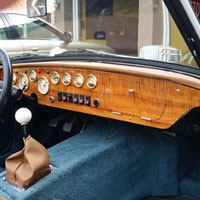
Custom
Dashboard
Dashboard
Special
Miata Seats
Miata Seats
Tremec 5-spd
Transmission
Transmission
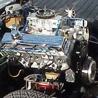
383cid
Installation
Installation
Front
Suspension
Suspension
Rear
Suspension
Suspension
Motor
Mounts
Mounts
Frame
Modification
Modification
Updated:
Fri 16 Apr 2021